

A safe insert is not chosen by foam name or density alone: it must control shock, vibration, movement, moisture, static and contact loads for one specific component. By the end, you will be able to define the component’s load case, specify its cavity and retention features, compare foam constructions, and set acceptance criteria for a finished package.
Key takeaways
- Select foam by load case, support area and drop energy—not density alone.
- Calculate firmness and thickness from the component’s weight and contact geometry.
- Cushion fragile interfaces without concentrating force on narrow edges or connectors.
- Test the completed package under drop, vibration, static and environmental conditions.
Choose the foam from the load case, not the density label
A component’s mass, support geometry and drop energy decide the foam—not the density label. Static stress equals component weight divided by effective supporting area. Narrow ribs, small contact lands and unsupported cavities reduce that real load-bearing area, even when the insert footprint looks large.
| Foam family | Density, firmness and cell structure | Compression set and resilience | Intended load |
|---|---|---|---|
| PU | Wide range; usually open-cell, with formulation controlling softness and recovery | Often comfortable cushioning, but verify long-term set | Light, irregular or vibration-sensitive parts |
| EVA | Closed-cell grades with adjustable density and firmness | Low moisture uptake; recovery depends on grade and compression | General industrial inserts and moderate loads |
| EPDM | Closed-cell elastomer; firm grades tolerate demanding environments | Good resilience and environmental resistance | Repeated handling, outdoor exposure and higher retention demands |
| Kluft | Treat the designation as a specific formulation, not a performance guarantee | Confirm its tested set and recovery data | Use only after matching its load-deflection data to the component |
| Crosslink foam | Uniform closed-cell structure; density and firmness vary by grade | Good recovery and clean, durable surfaces | Reusable inserts, machined cavities and sensitive finishes |
Two foams with the same nominal density can transmit different shock because formulation, cell structure, thickness and test strain rate differ. Compare cushion curves showing transmitted acceleration against static stress, thickness and impact velocity. Loading below the useful range can permit movement and bottoming out; loading above it can transmit high acceleration.
Thickness supplies crush distance, while density and formulation change load-deflection behaviour. Choose the cushion curve at the expected impact velocity, not a catalog compression value.
Calculate firmness, thickness and the cavity geometry
Start with the load case, not the foam label. Record mass, centre of gravity, drop height, drop orientations, vibration exposure, allowable acceleration and allowable deflection. Static stress equals component weight divided by effective supporting area, but a narrow rib or small contact land may carry the load while the rest of the footprint does nothing.
Use the foam’s cushion curve at the expected impact velocity: excessive softness can bottom out, while thin, stiff Foam Packaging can transmit excessive shock.
| Type | Locates the component | Best use | Main limitation |
|---|---|---|---|
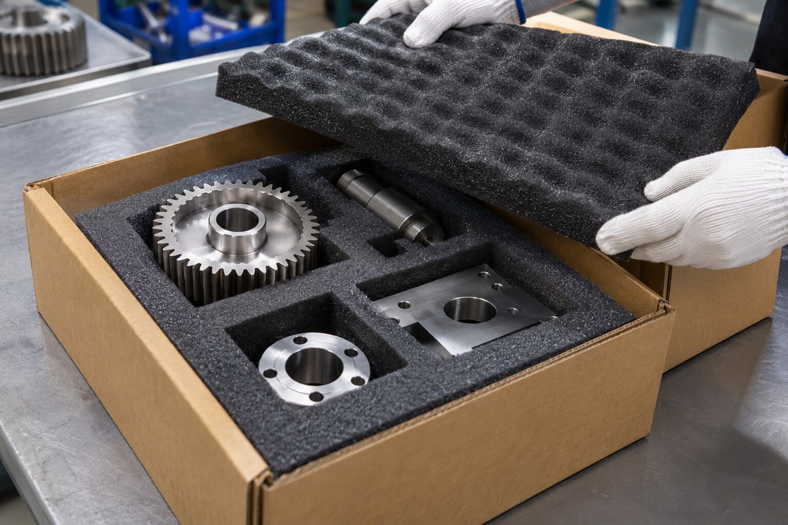
| Fitted insert | Defined cavity, restraint and orientation key | Repeated handling and known components | Requires measured dimensions and controlled tolerances |
| Loose foam fill | Fills voids around contents | Irregular contents or mixed loads | Less repeatable positioning and load transfer |
Specify the insert from these measurements:
- Overall component envelope and required orientation; record every cavity length, width and depth, plus wall thickness and corner radii.
- Controlled clearance for thermal expansion, dimensional tolerance and removal; a tight cavity can preload fragile sections, while excess space permits impact and fretting.
- Lead-in radii, finger pockets or pull tabs, an orientation key and enough access to remove the part without forcing it.
- Lid compression and retention force; do not treat compression as cushioning unless the foam transfers that load through a structural area.
- Post-compression cavity dimensions after sustained storage or stacking. Compression set and creep can reduce clearance and support force, especially at elevated temperature. Recheck the fit after the exposure, not only on the first assembly.
Protect fragile interfaces without creating new load points
Place retention lands on structural load paths: support robust housings and frames, not connectors, switches, seals, lenses, thin cast sections or painted faces. Retention prevents rattling, escape from the cavity and impact with the container; cushioning manages drop shock.
Do not use a hard point that sends a drop directly through the product, or a cavity so tight that it preloads fragile sections and loses clearance during thermal expansion.
Protect machined surfaces, optical lenses and plated finishes with generous radii, low-abrasion contact surfaces, and a barrier film or nonwoven interface where contact could mark or contaminate the part. Keep connectors clear of cavity walls, stop switches from continuous depression, and prevent sharp edges from cutting the foam.
Foam construction changes the risk profile:
| Option | Repeated handling | Dust and liquid | Compression recovery and storage |
|---|---|---|---|
| Open-cell polyurethane | Comfortable contact, but inspect for tearing and fatigue | Holds dust and absorbs liquid more readily | Can lose support after sustained compression |
| Closed-cell polyethylene or polypropylene | Better resistance to repeated handling and surface damage | Sheds less dust and resists liquid absorption; cuts and seams remain moisture paths | Usually retains clearance better, but verify creep and compression set |
For corrosion-sensitive Industrial Product Protection, evaluate the foam with the complete moisture-control system, including seams, cuts and compression damage. A foam that cushions well can still allow moisture to reach the component.
Control static, contamination and environmental change
Ordinary insulating foam is not automatically safe for electronic assemblies. Specify dissipative or conductive foam, shielding bags, grounding provisions and isolation from charge-generating surfaces when electrostatic control is required. Use ANSI/ESD S20.20 as the programme reference where applicable, but verify the foam’s electrostatic properties separately from its cushioning performance.
Check the material for contamination risks before approving it for Industrial Product Protection:
- Particle generation and abrasion at every product contact
- Plasticizer migration and chemical compatibility
- Odour and outgassing
- Compatibility with optical lenses, vacuum components, painted or plated surfaces, elastomers and clean assemblies
- Barrier film or nonwoven protection where direct foam contact is unsuitable
Qualify the package against hot-truck exposure, cold-soak conditions, humidity and repeated temperature changes. Temperature can alter stiffness, dimensions and recovery, so a fit that passes at room temperature can loosen, shrink or become too rigid in service.
Define whether the Packaging Solutions design is one-way or reusable. For reusable packaging, document the cleaning method, inspection interval, allowable tears or deformation, replacement criteria and maximum cycles. Include folding, abrasion, repeated loading and contamination in that assessment.
For long-duration compression or stacked storage, measure post-compression cavity dimensions and retention force. Initial fit alone cannot show whether creep or compression set will eventually release the component.
Validate the finished package and choose a practical build method
Prove the insert with the complete package, then choose a build route that matches volume and revision frequency. Test the product, Protective Foam Inserts, inner and outer containers, closures and accessories together—not an empty carton or insert alone.
Select an ISTA distribution test or ASTM D4169 schedule for the package mass and actual hazards, such as drops, vibration and compression. ASTM D4169 and ISTA provide test frameworks, not universal pass/fail guarantees. Define acceptance criteria before testing:
- No functional failure
- No connector disengagement
- No critical cosmetic damage
- No permanent deformation beyond your stated limit
- Acceptable post-test fit and retention
A generic sequence can pass while a connector fails or the component no longer fits.
| Build method | Strength | Trade-off |
|---|---|---|
| CNC-machined or waterjet-cut | Fast prototypes, low volumes, frequent revisions | Higher unit cost and possible scrap |
| Die-cut | Efficient repeat production with simple profiles | Tooling cost and limited cavity geometry |
| Molded | Consistent three-dimensional cavities at volume | Higher tooling cost and longer setup |
| Laminated | Combines materials or layers for complex support | More process steps and seam control |
Compare tooling cost, lead time, cavity tolerance, scrap rate and revision flexibility. Shri Ram Enterprises can coordinate the measured component, material choice, cavity drawing, prototype and production method as one specification instead of supplying generic Foam Packaging.
Before release, require a drawing, revision number, material properties, inspection points and test report for the chosen Packaging Solutions.
Related products
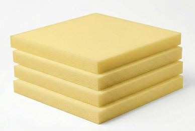 | PU Foam PU Foam is a versatile cushioning material used for protecting products against impact, vibration and movement during storage and transportation. View product → |
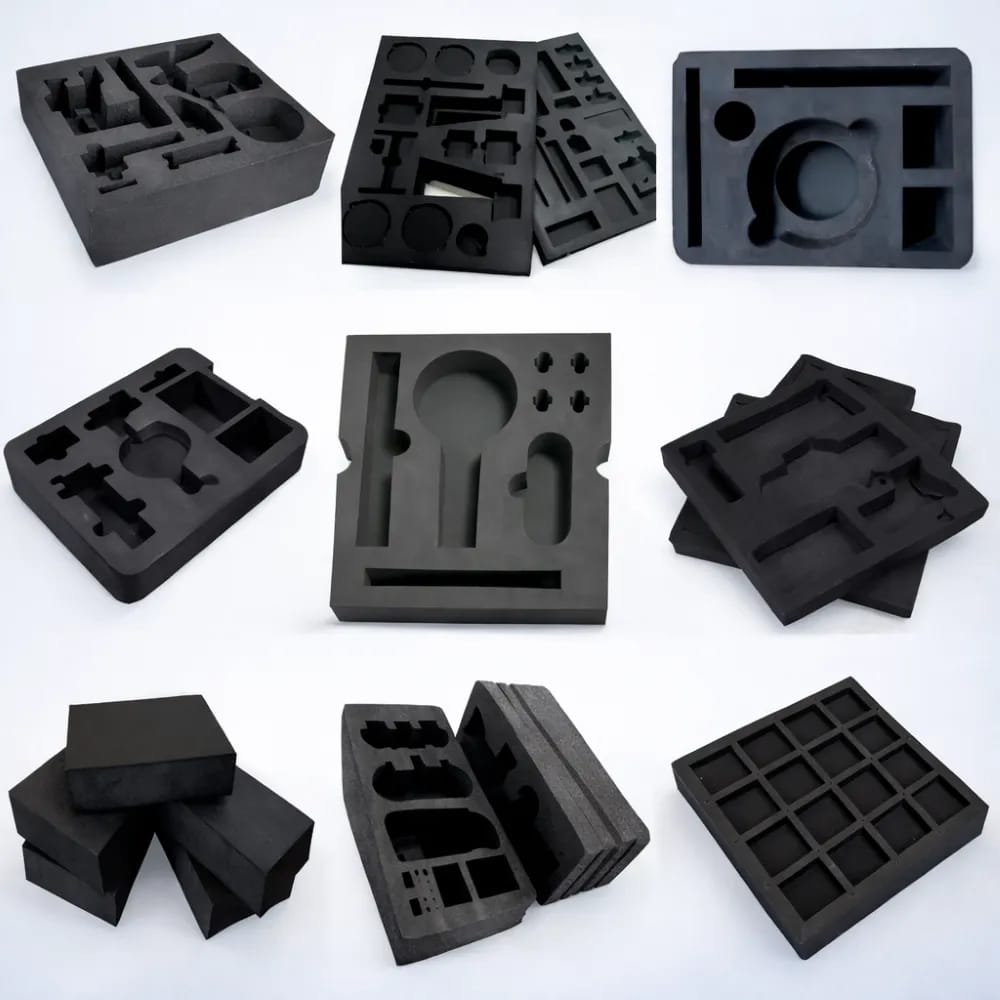 | EVA Foam EVA Foam is a flexible and resilient material widely used for custom protective inserts and cushioning applications. View product → |
Frequently asked questions
How should you choose foam for industrial protective packaging?
Choose it from the component’s mass, effective supporting area, support geometry and expected drop energy rather than density alone.
How do you calculate foam firmness and thickness?
Start with the component weight and actual load-bearing contact area, then size firmness, thickness and cavity geometry around the resulting stress and impact loads.
How can foam inserts protect fragile interfaces without causing damage?
Keep narrow ribs, connectors and small contact lands away from concentrated loads by distributing support across suitable surfaces and shaping the cavity around the component.
What should you check before approving a finished foam package?
Check static control, contamination risk and environmental changes, then validate the complete package with drop and vibration testing using a practical manufacturing method.
Related products
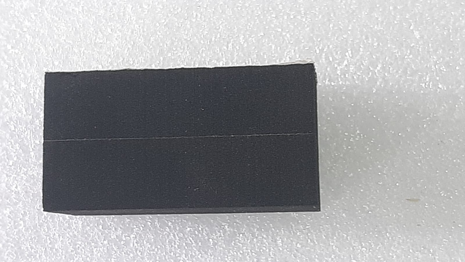 | EPDM Foam EPDM Foam is a flexible foam material suitable for applications requiring cushioning, protection, sealing and resistance properties. View product → |
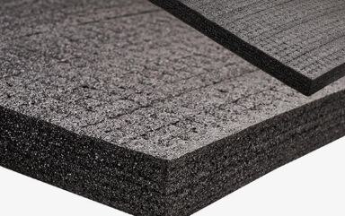 | Kluft Foam can be used for customized cushioning, protective packaging and product-support applications. View product → |
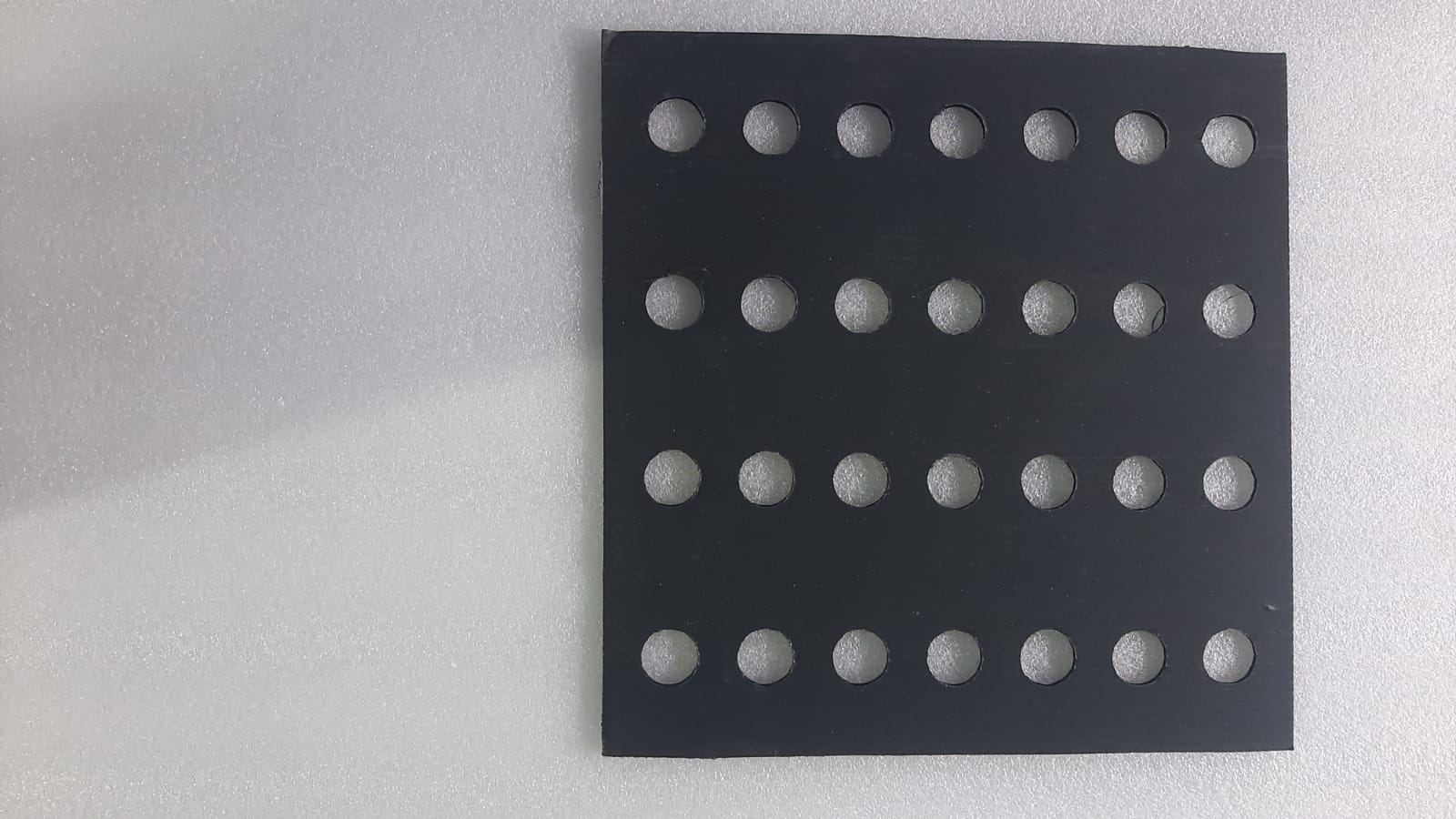 | Crosslink Foam Crosslink Foam is a durable closed-cell foam material used for cushioning, shock absorption and protective packaging. View product → |